Concentrators
HP-VFCO Concentrator
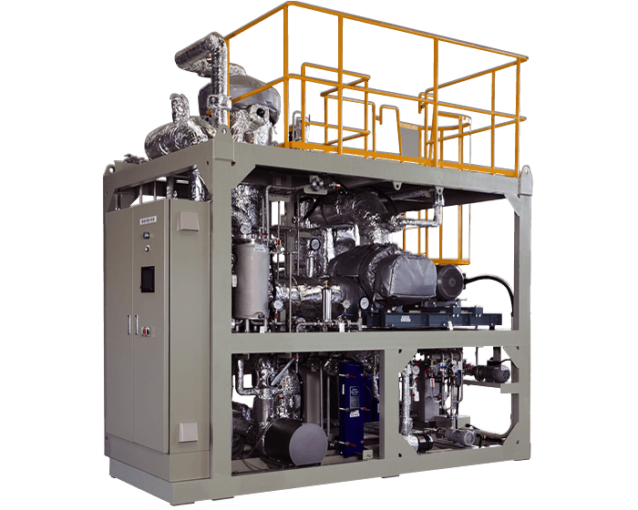
Features
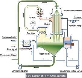
- The heating unit of the evaporator is of vertical tube type, and a circulating liquid is flowed down inside the tubes. The circulating liquid is boiled and evaporated by the heating steam outside the tubes, and flowed down to the flash room in high-speed dual-phased stream together with evaporated steam. The liquid separated from the evaporated steam in the flash room is returned to the upper part of the heater by the circulation pump. Mist is separated from the evaporated steam in the flash room and subjected to adiabatic compression by the steam compressor to change into heating steam, which is condensed after the heat exchange with the circulating liquid and then recovered as condensed water.
Main Features
Various types of liquid properties are supported by the high-compression type steam blower.
High concentration can be performed, which supports liquids with a high degree of boiling point elevation and liquids with strong contamination and scaling properties.
Energy saving by high heat-transfer performance
It has a high heat-transfer performance by high-speed dual-phased downflow in the heat-transfer tube, which realizes the ultimate energy saving.
Excellent maintenance which can also be used as sanitary equipment
CIP cleaning can also be performed. The structure allows the heater and flash room to be disassembled and inspected easily.
Compact design and reasonable equipment cost
It is based on the design concept, minimum necessary simple and compact design, and provided at reasonable equipment cost.
標準仕様
The following specifications are based on operations of dilute salt water at the 10 x concentration rate (with reference to weight).
| Model | Amount of evaporation [ton/day] | Steady-state electricity [kW] | Electric consumption [kWh/ton] | CO2 reduction [ton-CO2/year] | Installation area [mm×mm] | Height [mm] |
|---|---|---|---|---|---|---|
| HP(R)-VFCO I | 2.6 | 8~10 | 73~92 | 145 | 1,400×2,200 | 2,800 |
| HP(R)-VFCO II | 5.4 | 10~17 | 44~75 | 284 | 2,000×3,200 | 3,650 |
| HP(R)-VFCO III | 9.5 | 15~28 | 37~71 | 423 | 2,300×3,700 | 3,800 |
| HP(R)-VFCO IV | 18 | 28~43 | 38~58 | 716 | 3,500×4,500 | 5,000 |
| HP(R)-VFCO V | 25 | 40~60 | 38~58 | 1,078 | 4,000×5,500 | 6,500 |
| HP(R)-VFCO VI | 36 | 60~85 | 38~58 | 1,623 | 4,500×6,000 | 6,500 |
Note: The electric consumption includes all the consumptions by the motors and heaters for the equipment described in the above flow diagram.
*The above specifications are subject to change without advance notice. The electric consumption will vary depending on treated liquids.
*The CO2 reduction indicates the difference with the amount of CO2 generated from the single effect concentrator which uses steam. The annual operating days are assumed to be 300 days.
*The exterior panel is optionally available.